Creating a linear polymer
Description
Scope: the basic steps to create a polymer from scratch are included in this tutorial.
Difficulty: easy
Time required: 10 minutes plus the computation time, which depends on the availability of the computational resources.
First steps
NEXTMOL Builder allows the user to design polymers in an intuitive and user-friendly way and to export the system to NEXTMOL Modeling. In this tutorial, different linear polymers are designed from scratch. We encourage the reader to visit the Introduction to the scientific language page for a brief review of the most important concepts regarding polymers. Upon access to the home page of the platform the dashboard is displayed (Figure 1), where a summary of the most recently used building blocks, molecules and systems is presented.
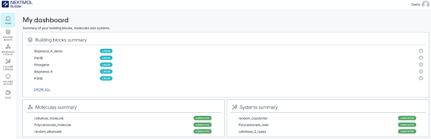
Figure 1: Main page of NEXTMOL Builder.
In the upper right corner, the user information is shown, allowing to either access the account information or log out. In the left panel, a menu displays the different sections of the builder. The ‘Home’ icon redirects the user towards the initial webpage. The ‘Building blocks’ icon allows the user to list the available monomers along with their characteristics and also to create a new building block. Clicking on an existing building block will show its relevant chemical information. The ‘Polymer Builder’ takes to a six-step procedure that enables the creation of any polymer from the monomers available in the ‘Building blocks’ section. The ‘Molecules Catalog’ and ‘Systems Catalog’ sections contain the list of systems that have been designed in the platform, corresponding the former to systems that contain a single molecule and the later to systems that contain two or more molecules. The ‘Docs’ icon will take the user to the documentation of the platform, where a more thorough description of NEXTMOL Builder may be found.
Creating a new monomer
Clicking on the ‘Building blocks’ icon will show the list of available monomers. The user is free to select any of the provided monomers to build the polymer later on, but here we will show how to create polyethylene, a popular polymer. The chemical formula of a laureth sulfate is CH3(CH2)nCH3, where n is the number of repeating units of the ethyl moiety. Therefore, we may click on ‘Create block’ and select a linear one. The ‘Name’ field must be filled with the name of the repeating unit, in this case we will use ‘Ethyl’. Then, in the ‘Parameters’ section, we can either select ‘Open structure editor’ or ‘Enter SMILES’. The first one will open a window that allows to draw the chemical structure of the desired monomer, while the second one allows to enter the Simplified Molecular Input Line Entry System (SMILES), a code that may be conceived as a sketchy way of formulating. It is not necessary to do both operations,one of them will be enough. The SMILES code of the ethyl moiety is simply C([*:1])C([*:2]).
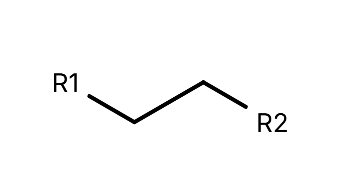
Figure 2: Chemical representation of the repeating unit 'ethyl'.
[*:1] and [*:2] (R1 and R2 in Figure 2) are the representations of the connections towards the head and the tail of the polymer respectively, i.e. any polymer is growing in the direction [*:1] to [*:2]. A head [*:1] must always be connected to a tail [*:2] in non-terminal monomers, while in terminal monomers we must define what groups are capping off the polymer. In the case of polyethylene, the head and the tail of the terminal ends correspond to hydrogen atoms (SMILES code: [*:2][H]). After the definition of the building block and the terminal ends, optionally a description can be provided. Clicking on ‘Create building block’ will save our progress.
Creating a linear homopolymer
Now we can go to the ‘Polymer builder’ section in the left menu to build polyethylene, a linear homopolymer. This can be achieved through a six-step (1)-(6) process that is described next.
(1) We can click on the icon ‘+’ that will appear when placing the mouse on the ethyl item to select the building block.
(2) Clicking on ‘Next’, in the lower right corner, we can create a segment, i.e. a pattern of building blocks. Since we are building polyethylene, we can create a segment called ‘20 replicas of ethyl unit’, select the ethyl moiety and specify 10 units in the ‘Occurrence’ field. By clicking on ‘Create segment’, the segment will be saved in the menu on the right side.
(3) In the next step, we will build the polymer. A name, in this case polyethylene, and a force field must be chosen. Two different force fields are available: GAFF, which is recommended in general for organic systems, and GLYCAM 06j, which is recommended for polysaccharides. After selecting GAFF, a segment and its occurrence must be indicated. Note that since we created a segment of 10 monomers of ethyl unit, our polymer can only be formed by a number of monomers that is a multiple of 10. After writing ‘10’ on the occurrence property, we can save a polymer chain formed by a total of 100 repeating building blocks.
(4) Then, the system setup is prepared through the definition of the cell that contains the system. We can directly set the size of the orthorhombic cell through the length of the sides or through the density of the system, which will size the cell according to the number of polymers we add in the box. The selection of the number of polymers that conforms the cell is not completely free. In GPU-run molecular dynamics the cell must have minimum size, otherwise the program will not be able to propagate the calculation. If, for example, we put a single polymer in the box the calculation might fail. Thus, we can place 10 polymer chains with a density of 0.5 g·cm-3. Underneath the cell dimensions there is the 'Hard Walls' option. If turned on, an artificial potential will avoid the expelling of molecules through the Z-axis of the cell, while, if turned off, periodic boundary conditions will be applied in the Z-axis. Perdiodic boundary conditions on the X/Y axis are always turned on. This option is useful for the creation of polymeric surfaces. However, since this is not the case, we can keep it turned off, save the system and jump onto the simulation protocol.
(5) In order to provide a better and more realistic structure of the system, additional steps involving computations are needed. Default settings for the energy minimization and the molecular dynamics will work just fine for most cases. Save the settings and click on next.
(6) In the final step, we need to name the system and to review that the information that is shown is correct. In our case we can call it ‘10 chains of polyethylene’. Saving will lead us to the Systems Catalog, where we can see our chemical systems that are formed by multiple units, in this case 10 chains. Under the section ‘Actions’, we can click on ‘Start processing’ to perform the minimization and molecular dynamics. Depending on the availability of computational resources, this could take a while. The calculation should finish successfully and the status should display ‘completed’. The ‘Actions’ column will now allow to download the files of the system, containing the information of the system, its geometry, its topology and the output of the platform. Molecules or systems with 'completed' status will be easily importable from NEXTMOL Modeling.
Creating a linear copolymer
The generation of a linear copolymer is almost identical to the previous section. Thus, for the following cases we will indicate which step is modified.
(1) At least two different building blocks must be selected in the ‘Polymer builder’ section. For example, ethyl and P3HB could be added to the list of building blocks.
(2) In the segments step we click on ‘Add linear block segment’, where we can choose the components of the segment. At this point, any building block may be added to the list more than once. For example, we can create a segment which is composed by ethyl-P3HB-ehtyl-ethyl-P3HB. In order to show that the complexity of the polymers can increase rapidly, we can introduce a second segment P3HB-ethyl-P3HB.
(3) Then, we can create a polymer by concatenating different segments, as one ethyl-P3HB-ehtyl-ethyl-P3HB, two P3HB-ethyl-P3HB and another ethyl-P3HB-ehtyl-ethyl-P3HB. The remaining steps are identical to those described in the ‘Creating a linear homopolymer’ section of this tutorial.
Creating a linear random copolymer
If the user intends to introduce some degree of randomness in the polymer, this can be performed through the construction of a random segment. Following the procedure described in the previous section until step (2), upon selection of ‘Add linear random segment’, will allow us to add two or more building blocks and to select the ratio of each monomer. For example, if the user intended to create a segment of 59 monomers with a 60% of ethyl and a 40% of P3HB, the multiplications 59·0.6 and 59·0.4 yield the values that must fill the ratio fields, 35 and 24 respectively. Then, the user can just write ‘1’ on the building blocks multiplier to obtain a segment of 59 monomers with the desired number of building blocks, as shown in Figure 3. The remaining steps can be followed as in the previous sections.
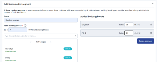
Figure 3: Design of a random segment in step (2).